3 application case
3. 1 processing of hook forging model cavity
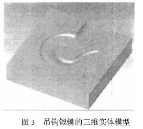
The hook forging die is a typical HAL F mode, the cavity is symmetrical up and down, and the 3D solid model of the lower die is shown in Figure 3. The blank has a boundary dimension of 240 mm × 240 mm × 60 mm and the upper and lower planes and surrounding contours have been finished. It is now necessary to complete the positioning hole and the entire cavity processing on the machining center, and the resulting processing steps are as follows:
(1) Roughing is performed in two steps by depth
Extracting the contour of the cavity, using POCKET-CONTOURROU GH + FINISH, the cutter adopts a flat-end milling cutter with a diameter of Ø12 mm, the machining depth range is 0~ - 1. 50 mm, and the edging groove form is finished once in the form of SPIRALCU T finishing
The rest is WCU T-CONTOUR ROU GH, the tool is still a flat-bottomed cutter with a diameter of Ø12 mm, the machining depth range is -1.5 mm to minpz, and the contour of the SPIRAL CU T is used for roughing of the cavity. Since the flat-bottomed cutter cannot be machined to a relatively flat surface at the bottom of the cavity, it is necessary to use a ball cutter to perform secondary roughing of the cavity.
(2) Semi-finishing
With WCU T —CONTOUR ROU GH , the tool uses a ball end mill with a diameter of <10 mm. The processing parameters select SPI2RAL CU T, WITH STOCK, BETWEEN LAYERS : ON SRF to process the residual margin at the bottom of the cavity.
(3) Finishing
With WCU T —CONTOUR FINISH , the tool uses a ball end mill with a diameter of <6 mm. Processing depth range - 1. 50mm ~ minpz, processing parameters choose SPIRAL CU T, BE2TWEEN LAYERS : HORIZ. Sub-regional machining based on the results of automatic slope analysis is used. The steep faces are processed by equal height, and the flat faces are finished by face-to-face circling.
(4) Root processing
With REMACHIN - CL EANUP , a ball end mill with a diameter of < 4 mm is used. The processing parameters are selected PREV. TOOL=BALL6, SPL IT HORZ VERT, which is mainly used for clearing the roots of the hook lugs and removing other residues with small local radius of curvature.
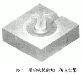
After the above process, the processing simulation results of the hook forging die are shown in Fig. 4.


3.2 Electrode machining of the button die of the copier
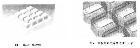
The electrode model of the button model cavity is shown in Fig. 5. The boundary of the blank is 100 mm × 85 mm × 35 mm. The upper and lower planes and the surrounding contours have been finished, and the machining depth ranges from 0 to - 15 mm. Now it is necessary to complete the processing of the positioning hole and the entire cavity on the machining center, and the resulting processing steps are as follows
(1) Roughing is performed in two steps by depth
Using the WCU T —CONTOUR ROU GH procedure, a flat-bottomed cutter with a diameter of Ø10 mm is used to machine a depth range of 0 to -15 mm, and the blank amount around the button group is removed by the STOCK SPIRAL cutter.
Using the WCU T-CONTOUR ROU GH process, a flat-bottomed cutter with a diameter of Ø4 mm has the same machining depth range as above. Select WITH STOCK to remove the blank margin between the buttons that were not removed in the previous process.
(2) Semi-finishing
Due to the uniform blank balance after roughing, the WCU T-CONTOUR FINISH can be used directly for semi-finishing, using a ball-end milling cutter with a diameter of Ø4 mm. The inter-layer processing parameters are BETWEEN LAYERS: HORIZ, PARALL EL CU T, which adopts automatic sub-area processing, the sides of the electrodes are processed with equal height, and the upper and lower surfaces are finished with horizontal cutting along the surface. All facets are selected for the working plane, SRF OFFSET = 0, and the electrode surface is cut to the model size.
(3) Finishing
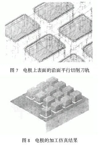
In order to supplement the discharge gap, it is necessary to overcut different electrode faces. Using the WCU T —CONTOUR FINISH procedure, the tool is still a 4 mm diameter ball end mill. By setting the different colors on the side and upper surfaces of the electrode on the model, and then using the BY CRITERIA option during the process of defining the part face, select the side of all electrodes to be PART SRF and the top and bottom surfaces to be PART 2 SRF. Then set SRF. OFFSET = - 0. 15 , PART2 SRF. OFST = - 0.08, respectively, to form different overcuts on the electrode surface. Processing parameters select BETWEENLAYERS: HORIZ, PARALL EL CU T. The contoured tool path on the side of the electrode is shown in Figure 6. The parallel cutting path on the upper surface of the electrode is shown in Figure 7.
After all the above processes are completed, the electrode simulation results are shown in Figure 8.
In the above two cases, Cimatron's machining strategy for cavity mold parts was basically adopted, which achieved very good results in actual machining. At the same time, it is not difficult to find out from the above cases that only according to the characteristics of the specific processing object, appropriate adjustment of individual processes in the processing strategy and setting of appropriate parameters can make the processing both efficient and quality guaranteed.


Previous page
Spirit Level,Spirit Level Set,Digital Spirit Level,Small Spirit Level
SHANGQIU DING LIAN INTERNATIONAL TRADE CO. ,LTD , https://www.dingqitools.com