In this example, a part will be designed with a length that is closely related to the number of round holes on it, and the number of round holes n is used as a design parameter.
First we generate a 2D sketch with constraints, where the size constraints automatically generate system-defined parameters; then stretch them into solids; then add holes to create an array of holes, the array also automatically generates system-defined parameters; then builds between the parameters relationship.
Part parameterization
(1) Generate a sketch: This sketch can also be implemented by dragging a "key" from the "pixel" design element library and editing its section. Select the "key" in the "Picture" design element library and hold down the left mouse button to drag it into the design environment.
(2) Click the part again to enter the smart pixel state, then click the right mouse button and select “Edit Sketch Section†in the pop-up shortcut menu to enter the 2D sketch.
(3) Right-click the tangent symbol between the arc and the line at this time, select “Lock†to generate the tangency constraint; click the “Parallel Constraint†button in “Constraint†in the sketch ribbon, and then select two straight line. .
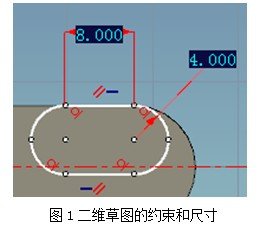
(4) Click the "Smart Label" button, then select the line, mark the line size, and then mark the radius of the arc. Then right click on the size, select "Edit", enter the length value 8 in the pop-up dialog box, OK. Then edit its radius value to 4 and confirm. Press the ESC key to exit the command.
The 2D sketch is shown in Figure 1. Click the "Finish" button. Two size parameters are automatically added to the parameter table at this time.

(5) Use the bounding box handle to edit the part height value to 8.
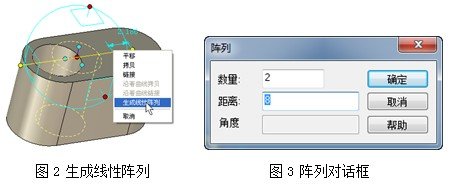
(6) Drag a hole-like cylinder from the "Graphic" design element library and change the size to length 5 and height 8. In the hole-like cylinder in the smart pixel state, click the 3D ball button or press F10 to open the 3D ball. Right-click the outer handle of the 3D sphere plane and select Generate Line Array from the pop-up menu when you release the mouse. Set in the Array dialog box as shown in Figure 7.15.

(7) After the array is generated, two parameters are added to the parameter: a proportional value parameter, where the value is 2, indicating the number of linear arrays; and a distance parameter, the value is 8, indicating the distance of the linear array. At this point, the parameter table has 4 parameters.
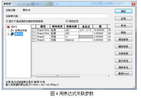
(8) Add an expression between several parameters in the parameter table. For convenience, change the parameter "Number" to "n1"; the expression corresponding to the parameter pD5 of the contour is filled in (n1-1)*8mm, ie The length of the straight line in the sketch section is the number of holes minus 1 and multiplied by 8, and then the value of n1 is changed to 3, as shown in Figure 4.

Right-click the distance value of the array, select Edit, and then enter -8 in the Distance field in the Edit Linear Array. Click the OK button to reverse the hole array. Then use a three-dimensional ball to translate the hole array.
Now you can determine the number of holes by modifying the number n1 of the hole array in the parameter table, and also determine the length of the key parts.
Tape measure is a commonly used tool in daily life, and it is one of the necessary tools for the family. Luban ruler, Feng Shui ruler, and Wen Gong ruler are also Steel tape measures. Steel tape measure is a common tool for construction and decoration.
Steel tapes can be divided into self-rolling tapes, braking tapes, and rolling tapes. Other names of steel tape measure are: steel tape measure, steel box ruler.
Rubber Tape Measure,30M Metal Tape Measure,Rubber Measuring Tape,Best Steel Tape Measure
Yucheng tengxu Measuring Tool Co., Ltd , https://www.txhardwaretools.com