In recent years, the single-machine numerical control system has been gradually replaced by the group control system (DNC) with microcomputer as the core. The manual programming is moving to the graphical automatic programming transition, and the CAD/CAM technology has been widely used in manufacturing technology. Thanks to the powerful drawing and editing capabilities of AutoCAD software and the open DXF data interface, it has become an important part of the graphics input platform and automatic programming. However, many current AutoCAD-based automatic programming systems are drawn in the order of processing. The automatic compensation of the tool path is not considered, and the machining direction needs to be manually set. For complex parts, it is often necessary to manually determine the drawing parameters, which has many inconveniences. This paper uses ARX development technology and VISUAL C++6.0 to carry out secondary development of AutoCAD, so that graphical input, editing, automatic tracing, NC programming, master-slave communication process are all completed under the AtuoCAD platform, and the wire cutting system is transformed into The goal is to achieve CAD/CAM integration.
2 system structure
The system adopts the master-slave control mode, in which the host adopts the mid-range microcomputer, and the slave adopts the single-chip system to directly control the wire-cutting machine. A host controls multiple slaves through the RS-485 interface, making full use of the powerful functions of the microcomputer to perform graphics input, output, and establishment of a database of cutting process parameters. The automatic programming module of the host converts the graphic data information into NC machining instructions, and transmits the machining instructions to the slaves, and the slaves execute in sequence to complete the machining process. At the same time, the slave machine feeds back data according to the host requirements, providing a basis for real-time control, automatic tracking and establishment of a process parameter database. The host software system includes six functional modules: graphic input, process parameter processing, automatic programming, simulation, tracking and communication (Figure 1).

Figure 1 host software system structure
3 automatic programming technology
The automatic programming module mainly solves the functions of automatic tracing, machining direction discrimination, automatic tool path compensation, etc., and realizes CAD/CAM integration. The process is shown in Figure 2.

Figure 2 automatic programming software flow chart
3.1 Get graphic data and generate basic processing closed loop
The DXF file generated by AutoCAD drawing input is used to obtain the processing entity feature information by using the feature-based information modeling method. What the system needs is the geometric information of the entity, so it only needs to read and process the ENTITIES Section of the DXF file and store the relevant feature information. Based on this information, the contour of the part and the topological relationship between its constituent elements are initially formed. CAD drawing entities are stored in the drawing order in the DXF file, regardless of the processing order. When deleting or adding an entity in the processing closed loop, since the entities in the DXF file are not stored in the order of processing closed loop, Reordering by endpoint connection to form a closed loop. In this way, the drawing and the machining are separated, and when the graphic input is performed by AutoCAD, the actual machining sequence does not have to be concerned, and the data input process is simplified. The system uses a double-linked list data structure to store entity information, and the data structure of the double-linked list is described in the literature.
3.2 Identify the processing direction
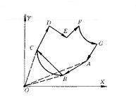
In this paper, the vector method is used to judge the processing direction. Next, the processing algorithm of the machining direction will be described by taking any processing closed loop shown in FIG. 3 as an example.
First traverse the double-linked list to find the nearest endpoint from the X or Y coordinate to the starting point of the machining, ie D=MIN(|x-x0|, |y-y0|). Let this point be point B, which is point A and point C in the front and rear ends of the list. It can be inferred that the connection of the two vectors AB and BC connecting the B point will uniquely determine the direction of the original figure.

Figure 3 is a closed loop diagram
The vector method is used to determine the direction of the triangle ABC. For ease of programming, the vector direction belongs to the quadrant according to the following principles. Let point A(xA, yA), B(xB, yB), C(xC, yc), then AB=OB-OA=(xBi+yBj)-(xAi+yAj)=(xB-xA)i-( yB-yA)j
When xB-xA>0, yB-yA≥0, AB∈I quadrant;
When xB-xA≤0, yB-yA>0, the AB∈II quadrant;
When xB-xA<0, yB-yA≤0, AB∈III quadrant;
When xB-xA>0, yB-yA<0, AB∈IV quadrant.
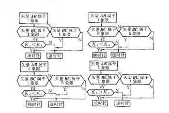
According to the selection principle of the starting point of the machining, it can be inferred that the vectors AB and BC cannot be in the same quadrant, thereby simplifying the judging process. The closed loop direction judgment process is shown in Figure 4. In Fig. 4, KI, KII, KIII, and KIV respectively indicate the slopes of the respective quadrant vectors. This method is simple in programming, fast in operation, short in program execution time, and can accurately realize automatic tracing.

Figure 4 vector method to determine the processing direction flow chart
3.3 Form the actual processing trajectory
When forming the actual machining trajectory, it is necessary to consider the influence of the concave, convex model, molybdenum wire diameter, discharge gap and machining direction of the processing object, determine the tool path compensation amount in the automatic programming system, and adjust the basic machining route. In order to ensure the processing accuracy. If the molybdenum wire radius is r molybdenum and the unilateral discharge gap is δ electric, the machining path offset compensation amount is
f=rmolybdenum+δ电(1)
The contour of the target workpiece is generally composed of a straight line and an arc (other curves can be obtained by fitting the line and the arc), so adjusting the actual machining path of the tool actually increases or decreases the radius R of the arc, and the straight line is at the normal. Shift f in the direction.
Let the points at both ends of the line be Ps(xs, ys), Pe(xe, ye),
The general equation for the original line is L: Ax + By + C = 0 (2)
The equation of the line after translation f is L': Ax+By+C'=0(3)
Among them (4)
A=ye-ys, B=xs-xe, C=xeys-yexs(5)
For arcs, R'=R±f(6)
The selection of the sign in equations (4) and (6) depends on the convex and concave modeling properties of the workpiece and the machining direction. See the reference [2] for adjustments in various situations. The system is accurate to 1 μm when performing the calculations. After adjusting each entity accordingly, the actual motion trajectory of the tool is obtained, thereby eliminating errors caused by process parameters such as tool and discharge gap, and improving machining accuracy.
In the actual machining, the contour of the workpiece may not be smooth, and corners, sharp corners, etc. may occur, which may cause problems such as wire breakage, short circuit, sag angle, and idle time. A transition arc (R ≥ f) may be added to make the processing track smoothly transition, thereby Protect molybdenum wire and improve processing efficiency. The system interpolates the entities in the processing order, stores the machining commands in a file, and sends them to the slave system for processing, thus realizing the integration of CAD/CAM.
4 Conclusion
The AutoCAD-based CAD/CAM technology introduced in this paper has been applied in our precision instrument factory, and the technical transformation and group control management of CKX-1 and DMK6732 CNC EDM machines have been realized. During use, the user only needs to be familiar with the basic drawing operation and draw input according to the design requirements without having to care about the machining process. Complex calculations and trajectory compensation are performed by an automated programming system to achieve separation of graphics input and processing. After drawing, the slave machine directly controls the slave machining, realizing CAD/CAM integration. The system also enables precise machining of complex workpiece contours. The system has a friendly interface and simple operation, and can accurately perform automatic tracing and tool path compensation, and the operation is stable and reliable, which reduces the burden on the operator and improves the processing efficiency.
Micro vacuum pumps are a series of brushed and brushless DC motor-driven pumps, which can be customized according to specific performance requirements. The miniature vacuum Diaphragm pump has large flow and long life. Applicable to various medical, environmental protection, chemical, biological engineering and other instruments and equipment. Ultra-small size, supports a variety of motors. Maintenance-free and long service life.
Mini vacuum pump,Vacuum pump,Vacuum diaphragm pump,Micro air pump
Changzhou Yuanwang Fluid Technology Co., Ltd. , https://www.ywfluid.com