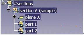
3.2.6 Section Information (#Sections)
The section information for all or part of the other parts associated with this part is stored here. These sections are for design analysis only and are not used for 3D model design.
Its substructure must also be named in English to distinguish it.
3.2.7 #black box part (black box part)
Black box parts such as body locks, shakers, etc., do not need to be designed for their internal structure and are only assembled to the parts on the body. All the data of these black box parts are stored here.
3.3 Design welding dot chart
The solder joint map is designed according to the welding method of the body. The level of the solder joint map should be consistent with the assembly level of the structure diagram.
Solder joint map name format:
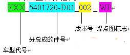
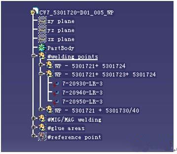
The substructures are: #welding points, #MIG/MAG welding, #glue areas, and #spray areas. As shown below:
3.3.1 #welding points(welding points)
This place stores the solder joint information during spot welding, and the substructures respectively represent the specific contents of the solder assembly relationship between different parts (or components) in the assembly.
The name of the substructure is WP plus the part number of all the parts involved in the weld. Such as WP-5301130+5301700+5014123.
Each solder joint under the substructure is named in order. Take a car solder joint as an example: 7-2501-LR-3. 7 is the model, 2501 is the 01th solder joint of the 25th layer, LR is bilaterally symmetric, and 3 is three pieces welded here.
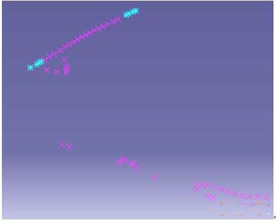
Representation of solder joints: When soldering two parts, the solder joint is represented by a purple x, and the triple solder joint is indicated by a light blue *. The left and right symmetrical solder joints only indicate the left side. Refer to the figure below.
3.3.2 Protective welding (#MIG/MAG welding)
Store information that requires protective welding. The specific shape of the weld is represented by a straight line or curve of 0.5 mm width. Expressed separately from left to right. The following figure shows the weld representation of the hinge using protective welding.

The name of the substructure is MIG/MAG plus the part number of all parts or components that need to be soldered here, for example: MIG/MAG-5701111+5401110/1120. Indicates that there are two welds, the weld between the part 5701111 and the assembly 5401110, and the weld between the 5701111 and the assembly 5401120.
3.3.3 glue area (#glue areas) and spray area (#spray areas)
a) Extrusion area (#glue areas)
Each extrusion site is stored separately in an open body. If the glue is squeezed left and right, the left and right data are in the same open body.
The extrusion route is represented by a colored tubular surface. The diameter of the tube is generally φ5. Special positions can be resized according to the situation. The following picture shows the extrusion position of a certain model:
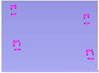
In addition, it should be noted that: the extrusion glue is divided into welding extrusion and coating extrusion. In order to give a difference, the two extrusion routes are specified in different colors, the welding extrusion is black, and the coating extrusion is white.
b) Spray area (#spray areas)
The result of spraying the PVC area exists in the spray areas under the #part definition. The method is represented by black grid lines where the area to be painted is required.
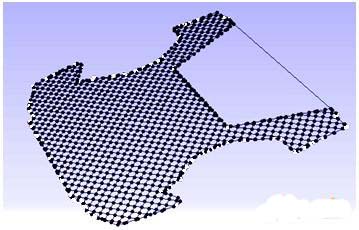
c) name
The extrusion area and the spray area are in the same file, using the same file name, the name is: project name plus sealing plus time. Such as: CV7-sealing-20040507.
3.4 Standard part design
Separate the nut, bolt diagram, and plastic clip from the part. When the part number is programmed, add L at the end of the part number to distinguish it from the part number. For example, 5301311-D01 indicates a part number, and 5301113L-D01 indicates that the part is a part number welded with a nut or bolt welding assembly.
Put the commonly used nuts and bolts into the standard parts library, call them in the parts that need to be welded or installed, and insert them in the correct position and direction. The precautions are:
a). Create a parts library in the PDM system for everyone to share.
b). The shape and size of the nut and bolt are consistent with the actual situation.
c). The state of the nuts and bolts (welding position, number, type, etc.) is consistent with the actual loading situation.
d). For parts with “L†part number, use the assembly file Catiaproduct to assemble the parts and the nuts and bolts welded on them.
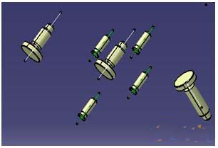
e). The part number of the sub-assembly with the "L" part number is: Model - _welding_nuts_studs_bolts - sub-assembly part number, only all the nuts and bolts in the sub-assembly are assembled. The figure below shows a partial bolt diagram of a sub-assembly of a certain model, which contains three types of bolts, and their status is the same as the actual situation.
3.5 Closed body motion check:
The calibration document for the body closure mechanism is named: part number of the part participating in the movement + part number + + + kinematic of the part participating in the movement. The 3D data of the parts participating in the motion are inserted under Product and the constraints are added. Then use the Digital-mockup/DMU-kinematic module in the CATIA software to parameterize and check it. The document contains all definitions and constraints for the institution and the range of motion.
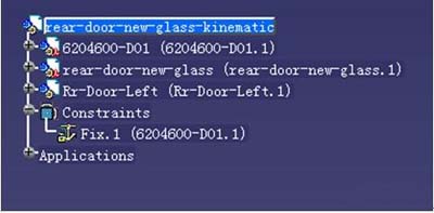
As shown above: shows the motion check of the back door shaker and glass. The data of the shaker, the back door glass and the left back door of the participating sports are respectively added under the document. And constrain the position of the shaker to check.
Nail file sandpaper sheet, Manicure sandpaper sheet, Nail filing sandpaper
Foshan Nate Abrasive Science & Technology Co.,Ltd , https://www.nateabrasives.com