With the increasing popularity of CAD/CAPP/CAM/PDM technology, computer 3D design will become the core and foundation of future manufacturing. Commonly used mechanical 3D design software is Pro/E, SolidWorks, UG, CATIA, Inventor and so on. These commonly used 3D modeling softwares, although their interface elements are different in form arrangement, operation method and some functions, are basically the same in the overall design of the modeling. For 3D modeling of general products, it is not important to use any CAD 3D software as long as you have mastered the correct modeling methods, ideas and techniques.
Computer 3D modeling is a process of transforming mental modeling language and computer interface elements. At present, 3D software learning generally pays attention to the memory and instance imitation of computer interface elements, ignoring the mental modeling thinking ability. The ability of mental modeling thinking is the key to guiding 3D modeling. Therefore, it is necessary to explore the theoretical thinking of 3D modeling, strengthen the system training in this aspect, and be able to cope with the learning of different software calmly, and more effectively memorize software commands under the guidance of correct thinking rules, to achieve quick entry and effectively improve modeling skills. the goal of.
1 three-dimensional configuration theory
Mechanical 3D design software is mainly based on feature-based solid modeling. Therefore, unlike traditional projection theory that guides 2D graphs, 3D modeling mainly uses the theory of constructive solid geometry (CSG) and geometric features of shapes. CSG is an analysis of the overall formation of an entity, that is, any complex entity can be regarded as a combination of simple unit bodies, similar to the body analysis method of the assembly in engineering drawing, and the object is decomposed into several primitive bodies (ie, unit cells). Boolean operations (collection, difference set, intersection) are generally used to achieve this combination. The thinking mode of this form analysis method is full three-dimensional, which is a three-dimensional simulation of the whole process of processing entities in the objective world. Psychological activity.
2 basic body modeling
2.1 Basic body decomposition
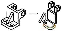
Traditional manual 2D or 2D CAD drawings are drawn with various lines. For the shape of the drawing, no matter what is drawn first, what is drawn later, the figure can always be drawn, so the importance of the order is not very prominent. Computer entity modeling is a collection of geometric features. The order of modeling is particularly important. If improper parts are arranged, it cannot be generated, or the generation process is too complicated. On the contrary, generating parts is simple and convenient (see Figure 1).

Figure 1 Basic body decomposition
For this purpose, it can be handled in a modular manner, with the basic body decomposition of the object. The principle of decomposition is: from the obvious degree of reflecting the main features of the shape and the size of the total volume and its main functions, it can be divided into two types of modules: superimposed basic body module and cutting basic body module. It can be subdivided in each module as necessary.
2.1.1 Superimposed basic body module
In the module, the basic body that embodies the main physical features and main functions of the entity and the relatively large proportion of the volume is firstly divided, and then a plurality of basic primitives are further divided according to the primary and secondary. The most important first primitive that is divided should be the basic body of the configuration, that is, the reference body that generates other primitives. It is worth noting that each single primitive module should be decomposed into the most easily used feature modeling methods (including stretching, rotation, lofting, scanning, etc.).
2.1.2 Cut-off basic body modules These basic bodies have features that cannot exist independently and must be added to the above-mentioned basic body series, such as holes, cavities, grooves, and the like. It belongs to the cut and the difference set.
2.2 Select drawing datum
The creation of primitive modules is an important step in modeling and the basis for modeling. The feature plane (ie sketched section) should be found first, and then the basic body modeling method should be determined to characterize the feature. It is worth noting that before creating these features, you need to perform spatial positioning of the primitives before drawing the section sketches.
The spatial localization of the primitives (ie, the determination of datum planes, lines, points, etc.) uses the base class features, which are auxiliary geometric features and do not produce entities. In choosing these reference features, it is necessary to analyze the mutual positions of the basic bodies that make up the part.
2.3 Modeling sequence
The modeling order should follow the principle of first big and then small, first outside and then inside, first down and then up; first real and then virtual, first "and", "cross" and then "poor". There are multiple primitives in a part that should be modeled from the largest, outermost, or bottommost primitive, as they are often the primary reference for the part. For internal structures, such as holes, slots and other cutting features, after all the superimposed primitives have been established (including "and" and "intersection" operations), subtract the cutting body by the difference set operation based on the above construction. Each primitive within the module. Features can be edited when creating basic features: feature operations such as arrays and mirrors.
3 pump cover three-dimensional design practice
3.1 Shape analysis
Decompose each basic body (the bottom plate has six holes, flanges, two blind holes, countersinks).
3.2 Modeling steps
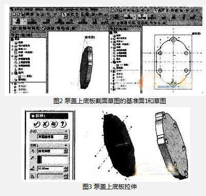
1) Basic base: Select the datum. Draw a sketch of the basic features; then select features: stretch, rotate, scan, or loft; as shown in Figure 2, the baseplate is stretched.

3M Measuring Tape,Waterproof Tape Measure,Stainless Steel Tape Measure,Plastic Tape Measure
SHANGQIU CHAOYUE MEASURING TOOLS CO., LTD , https://www.calibrateds.com