Now there are two most common ways to achieve LED dimming: PWM Dimming and Analog Dimming. Analog dimming adjusts the brightness of the lamp by changing the LED lamp current amplitude.
Obviously, the larger the current, the brighter the LED; the smaller the current, the darker the LED. Now the PWM dimming power supply is generally implemented in a two-stage structure. The first stage AC-DC output is a constant voltage and the second stage is DC-DC. The dimming function is implemented in the second stage through PWM. This makes the circuit more complicated. The dimming power supply adopts the analog dimming method, and the control IC adopts the LD7535+ATtiny24, which directly realizes the cross-flow constant voltage adjustable output. The following is the schematic diagram:
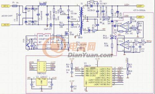
Actually, the dimming principle is very simple. The output current of the power supply is I = Vref/Rs. Vref is the reference voltage. Rs is the output current sampling resistor in series. To change the output current, Rs can be changed, or Vref can be changed. The designed power supply is used. It is the way to change Vref.
The specific idea is to output the PWM signal through the single-chip microcomputer. After filtering and dividing to obtain Vref, Rs is fixed, then the output current is controlled by the single-chip microcomputer. The resolution of the dimming is determined by the PWM bit number of the one-chip computer, Attiny PWM is 8 bits, so the stepping of the electric current is 500MA/256, it is about 2MA. The following is a simple analysis of the circuit:
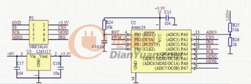
The control signal is sent to the MCU through P2, and U3 provides a stable 3.3V voltage for the MCU operation. The main task of ATtiny24 is to output the corresponding PWM signal on the PB2 pin according to the control signal. R25 and R26 divide the output voltage, and PA0 samples the output voltage through the ADC. The PWM signal output by the single-chip microcomputer passes through the following filter circuit to obtain a stable output voltage signal.
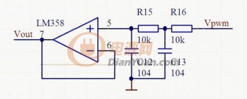
Since the power supply voltage of the microcomputer is 3.3V, Vout=Vpwm*D=3.3*D, and D is the duty ratio. Vout is further divided by R10 and R14 to obtain Vref.
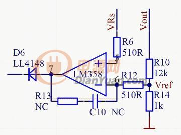
Vref and the output sampling resistor voltage VRs are amplified by the op amp LM358, and then fed back to the LD7535 via the optocoupler. Finally, the set output voltage and current values ​​are obtained. The other circuit parts are ordinary flyback power supply circuits and no more analysis.
Metallographic Mounting Machines
Hot mounting is ideal solution to get high quality, uniform size sample,as Well as short process time. lt is to use mounting compounds With certain pressure, temperature to make a sample.

Metallographic Mounting Machines,Mounting Specimen Preparation,Metallography Analysis Mounting,Metallurgical Sample Preparation Equipment
TROJAN (Suzhou) Technology Co., Ltd. , https://www.trojanmaterials.com