- Generally, fatigue crack growth can be divided into three phases: phase I (shot cracks), phase II (long cracks), and phase III (final fracture).
Fig. 1— Stages I and II of fatigue crack propagation.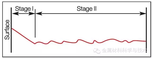
Stage I: Once the crack is initiated, it will expand along the maximum shear stress plane (about 45o), as shown in Figure 1. This stage is considered to be the first stage or the short crack initiation and expansion stage. The crack extends until it encounters an obstacle such as a grain boundary, inclusions or pearlite zone. It cannot accommodate the expansion direction of the initial crack. Therefore, grain refinement is a principle that can increase the fatigue strength of materials by utilizing the introduction of a large number of microscopic obstacles. The grain boundary, in the first stage of crack propagation, needs to overcome the grain barrier and cross the grain boundary. Surface mechanical treatments such as shot peening and surface rolling also introduce some microscopic obstacles because they cause the grain boundaries to be crushed.
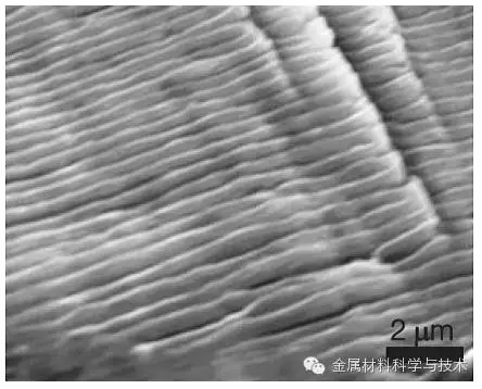
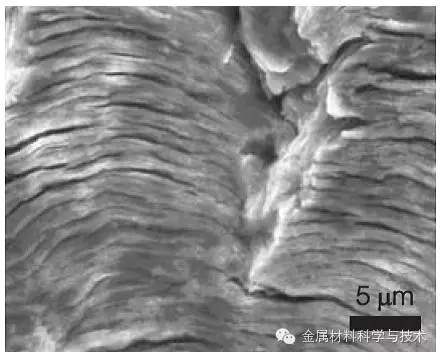
Fig. 2 — Fatigue striations in (a) interstitial free steel and (b) aluminum alloy AA2024-T42. Figure (c) shows the fatigue fracture surface of a cast aluminum alloy, where a fatigue crack was nucleated from a casting defect, presenting Solidification dendrites on the surface; fatigue striations are indicated by the arrow, on the top right side.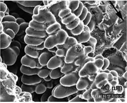
Stage II: Due to the crack propagation, the actual load rises, the stress intensity factor K increases, and slip occurs on different planes near the crack tip, thus entering the second stage. In contrast, the first stage crack propagation direction is at a 45 degree angle to the load direction, and enters the second stage. The crack propagation direction is perpendicular to the load direction and is at an angle of 90 degrees, as shown in FIG. A very important feature of Phase II is the ripple on the surface of the fracture. The terminology is called Striations, which needs to be seen with the help of scanning electron microscopy. Not all engineering materials will produce fatigue fuzz when they enter the second stage when fatigue occurs. Fatigue ridges appear in pure metals and some tougher alloys, such as as-cast aluminum alloys. In steel, this feature is often found in cold hardened steel. Figure 2 shows an example of a steel in a gap-free atom and an aluminum alloy. The mechanism of fatigue fading on the ductile metal fracture is: continuous passivation and resharpening of the crack tip as shown in Figure 3.
Fig. 3 — Laird's proposed mechanisms of striation formation in the stage II of propagation: (a) no load; (b) tensile load; (c) maximum tensile load; (d) load reversion and (e) compressive load.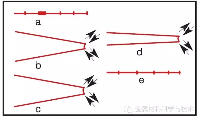
Stage III: Finally, when the crack tip stress intensity factor exceeds the critical stress intensity factor, the crack is unstable and rapidly expands. At this stage, the crack propagation is controlled by the failed static mode and is very sensitive to microstructure, load ratio, and stress state (planar stress loading or plane strain loading).
Macroscopically, the fatigue fracture can be divided into two main areas, as shown in Figure 4. The first region corresponds to the fatigue crack stable expansion and presents a smooth side because the dual fracture surfaces will rub against each other. Occasionally, a "beach mark" can be seen on the surface of the fracture, which is the result of a change in load, or because of the temporary stop of loading, or the introduction of compressive residual stress at the crack tip due to overload.
Final fracture: The other part of the fracture corresponds to the final fracture zone, exhibiting fibrous and irregular characteristics. In this area, the fracture can be either ductile or brittle. It depends on the mechanical properties of the material, the geometry of the component or the loading conditions.
The exact ratio of each zone depends on the actual load level. The higher the load, the smaller the proportion of the stable extended area, as shown in Figure 4. On the other hand, if the loaded load is small, the crack can extend beyond the critical stress intensity factor for a longer distance to reach the fracture toughness value of the material, resulting in a smaller instantaneous fracture zone, as shown in Figure 4(b).
Fig. 4 — Fatigue fracture surface: (a) high applied load; (b) low applied load.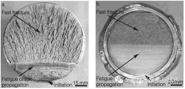
Ratchet pattern: The ratchet pattern is another macroscopic feature that can be observed on the surface of the fatigue fracture. These features usually occur in the case of multi-source cracking. When the cracks are in different positions, when they meet each other, a step appears on the fracture. Therefore, the number of ratchet patterns is a good indicator of the number of crack initiation points. Figure 5 shows the details of the wheel pattern on the fatigue fracture.
Fig. 5 — Ratcheting marks, indicated by the arrows, in a SAE 1045 shaft fractured by fatigue.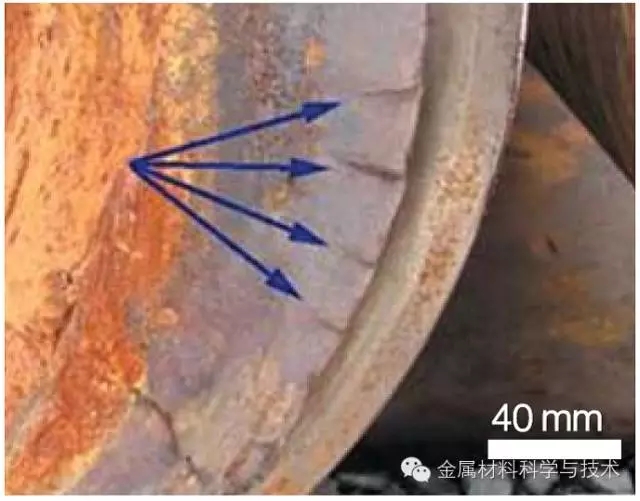
Expansion rate: Similar to the initial stage, many factors affect the rate of expansion of long fatigue cracks. Among them, the most important concern is the effect of load ratio and residual stress. Increasing the load ratio increases the long crack growth rate from the trend, as shown in Figure 6. Generally, the effect of increasing the load ratio on the Paris system is less than the impact of the near threshold and the near failure zone. Approaching the threshold stress intensity factor, the ratio R can be attributed to the crack closure effect.
Fig. 6 — Schematic representation of the R ratio effect on fatigue crack growth curves. The near threshold, Paris regime, and final failure regions are also indicated on the curves.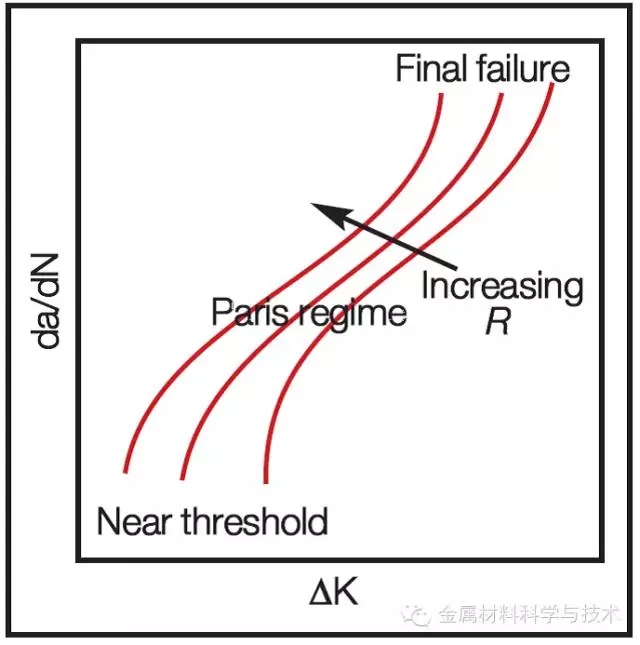
Several different mechanisms lead to crack closure and plasticity induced closure as shown in Figure 7. As the crack grows, the material that has been permanently deformed in the plastic zone now forms an envelope at the plastic zone of the crack tip. This causes the displacement constraint perpendicular to the crack surface to be released. This is not a problem when the crack is opened. However, when the load is lowered, the crack surface contacts and the crack is blocked before the minimum load comes. There are some other situations with this premature contact, as shown in Figure 7.
Fig. 7 — Crack closure mechanisms induced by: (a) plasticity, (b) roughness (c) oxide.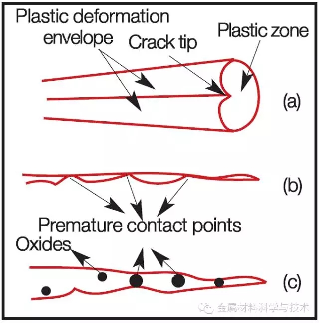
For most materials, the Paris system is considered "no closure and does not depend on the maximum stress intensity factor." And the crack growth rate is usually similar to the test under different R ratio conditions. Near final failure, when Kmax approaches KIC, the effect of the R ratio is related to the high monotonic fracture component.
Fig. 8 — Load ratio effect on Keff, in a fatigue cycle: (a) Kmin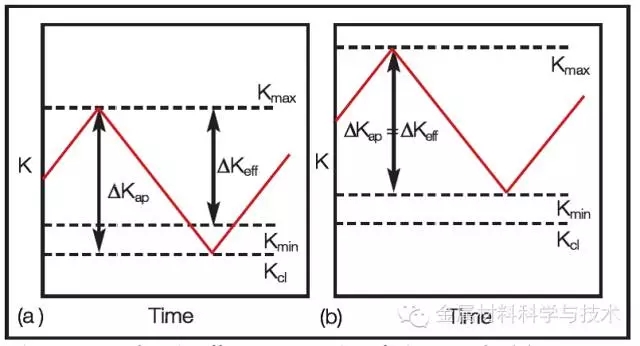
Kcl
Heilongjiang Junhe Building Materials Technology Co., Ltd , https://www.junhejiancai.com