Shadow shading is a problem often encountered. The photovoltaic power generation characteristics dominate, and the IV output characteristics of the components will appear multiple saddle shapes under the influence of shadows, due to the limited range of the MPP tracking voltage of the inverter and the limitations of the algorithm. Sex brings a deviation to the actual MPP voltage of the array of squares, which in turn leads to a loss of power generation. PVSYST photovoltaic system design software has a more complete array of partial shadow analysis capabilities, this article through examples based on PVSYST6.12 software for the loss of the shadow of the building part of the preliminary analysis and estimation.
1. The relationship between the power output of the module and the obstructed area
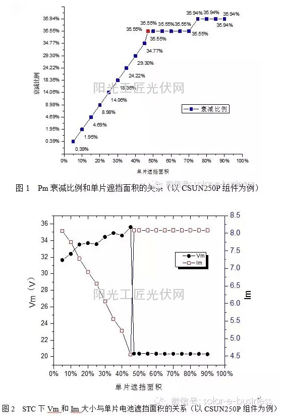
By using the PV MODULE gadget of PVSYST software and the CSUN-250P polycrystalline module as an example, the power output under the different shielding ratios of the single-cell battery under the STC can be obtained. From Fig. 1 and Fig. 2, it can be seen that when the shielding area is less than 47%, The way diodes are not turned on, and the Pm output and Im size tend to decrease linearly with the obstruction area. At 47%, the two switches occur because the bypass diode of the battery string where the obscured battery is located is now conducting. After the battery is short-circuited, the Vm of the entire module is reduced by one third after bypassing, that is, at about 20V, and the current Im becomes the normal operating current of the unshielded battery. The relationship between the Pm and the shielding area obtained through the simulation is more realistic. Indoor solar simulator shade shading test results. Therefore, when a local shadow occurs, it is bound to pull down the Vm of the entire string, which affects the maximum power point tracking of the inverter.
2. Analysis of the effects of shaded building shadows on array power generation
Here, a 10kw (20*2) PV array system is specifically simulated and the relevant parameters are configured as shown in Table 1. The PV array layout is shown in Figure 3.
As shown, each row of squares is 10 pieces, and 2 pieces are 20 pieces in total. There are 2 strings in total. The best row spacing is 2.81 meters. The inverter is a string inverter. There are two MPPT, to highlight the shadow of this influencing factor, add a high wall at a distance of about 1.76 meters to the left of the square, 4 meters in length, the highest point of the wall and the lowest point of the component border is about 3 meters, when the winter solstice sun height When the angle is low, the second row of the first series and the second row of the second series will be shaded by the shadows of the front row components, and the specific sheltered area will change as the orientation of the sun changes.
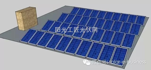
Figure 3 Photovoltaic array layout and location of building high walls
The shading of the PV array is related to the solar orientation. The PVSYST software can observe the shadow changes of 365 days a year. Here, representative days are selected, such as the spring equinox, summer solstice, equinox, and winter solstice. Solar radiation has a greater impact on power generation. When the light intensity is low, the power generation of the array is very low. Table 1 only lists the light intensity at the time of shadowing and the time and the corresponding light intensity at the beginning of the shadow at 16:30. With the passage of the time from winter to spring, the height of the sun changes, and the beginning of the shadow changes. Figure 4 to Figure 7 show the shadows of the four typical days at 15:00.
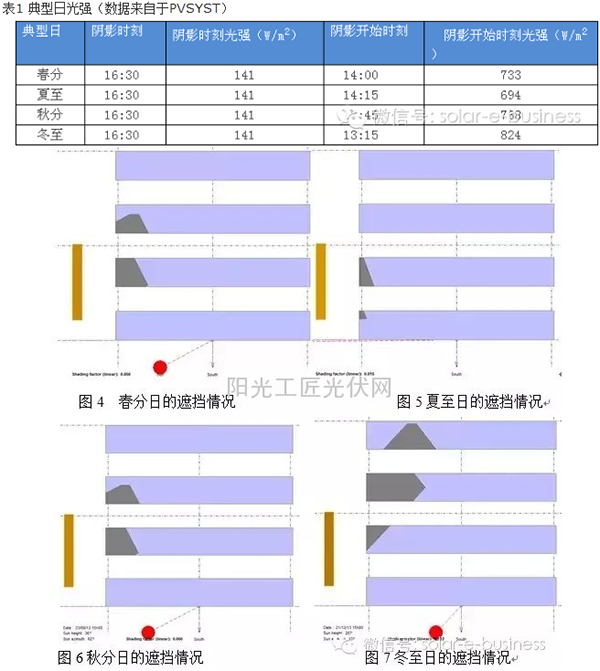
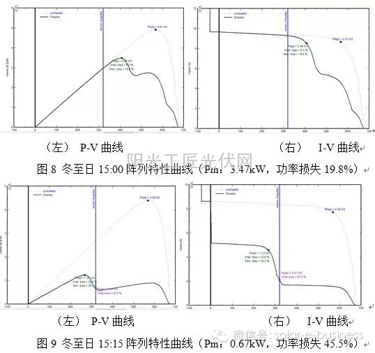
Different shadows will bring different IV curves. For example, at 15:00 pm on the winter solstice day, see Figure 7, in which some cells in the string have been blocked. Since the module contains a bypass diode, the IV characteristic curve will be The original single peak becomes bimodal or even multimodal, which causes the IV curve to exhibit non-linear, multi-peak characteristics. At this time, the photovoltaic array receives uneven illumination and there are 3 kinds of occlusion ratios. Therefore, 3 saddle shapes appear. Corresponding to the three peak Pm points, the MPPT voltage range of the string inverter in this example is 320V-800V. At this time, the MPP point is still within the MPPT voltage range, the maximum power point voltage is about 425V, and the Pm power is 3.47kW, refer to Figure 8.
At 15:15, the string MPP point is obviously outside the MPPT voltage range. Conventional maximum power point tracking strategies such as perturbation observation method, incremental conductance method, short-circuit current method, and open-circuit voltage method cannot be distinguished from the local maximum power point. The global maximum power point may be ineffective because the traditional algorithm in the MPPT range may mistake the local peak point of the output characteristics of the photovoltaic panel for the maximum power point. The point voltage is higher, the current is lower, and must be affected by shadows. A global scan can be performed to determine the true maximum power point. From the simulation results, the inverter performs a global scan within the MPPT voltage range. The actual selected MPP point is near the maximum power point of 280 V, that is, at the minimum value of 325 V, refer to FIG. 9 . It should be noted that the output characteristic curve of PVSYST simulation is the curve of two parallel strings superimposed.
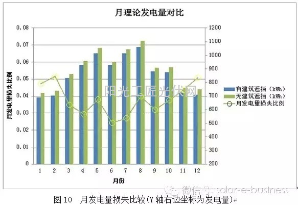
Through the software simulation of the theoretical annual power generation capacity of the array below the high wall of the building, the model is compared with the simulation of the other conditions when the high wall is removed and the other conditions remain unchanged. The results show that there is power generation during construction. About 10,346 kWh, without building shelter, the annual power generation is about 10,746 kWh, the building shadow loss power generation is 400 kWh, and the loss ratio is about 3.73%, of which the ratio of winter and spring accounts for a larger proportion. See Figure 10. As the installed capacity of the system increases, the amount of power generated by shadow losses will increase accordingly.
3. Summary and discussion
There is no very accurate calculation model and calculation software for the loss of the shadow of the building shaded by the array. Under the condition of shadow, the nonlinear variation and multi-peak characteristics of the PV special effect curve are brought to the maximum power point tracking band of the inverter. To challenge, PVSYST software can scan and search in the global MPP voltage range. At present, domestic string inverters already have this tracking ability, and the tracking algorithm is also constantly improving. The loss of power generation and the actual situation in the text obtained through analog estimation should be There are some differences, but it still needs further analysis and verification. If you have better ideas or different opinions, you can communicate together.
Organizer Travel Bags,Laundry Pouch Travel Bag,Travel Bags Organizer For Luggage,Travel Organizer Toiletry Bag
Dongguan C.Y. RedApple Industrial Limited , https://www.redapplebags.com