This paper takes the threaded joint design as an example to explore how to use AutoCAD and the high-level programming language based on AutoCAD platform to develop a software system method for designing, checking and drawing integrated parts that can be run on a microcomputer. Other parts can be modeled in this way. In this way, the engineer can automatically generate and print the design specification and part drawing through the computer by inputting some necessary parameters.
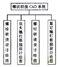
 Figure 1 Block diagram of the threaded CAD system |
- Threaded CAD system
- Related technology of threaded connection CAD
- The technical points of threaded CAD are:
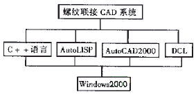
- Software development language: C++ language, AutoLISP, DCL;
- Software development platform: AutoCAD2000;
- Software hardware environment: one computer with 486 or 586 or above.
- The technical composition of the threaded CAD is shown in Figure 2.

Figure 2 Block diagram of the technical composition of the threaded CAD
According to the type of threaded joint, combined with the application of threaded joint design and drawing in engineering CAD, the design of the threaded joint and the drawing of the part drawing are divided into four modules, which are represented by block diagram 1.
- Threaded CAD application with AutoLISP and C++ programming
- Design user interface with dialog technology
- Thread design and drawing with integrated programming
- Processing of design results
AutoLISP is a LISP programming language that runs under the AutoCAD environment or is embedded in AutoCAD. It has strong graphics development capabilities. The language is integrated with the AutoCAD environment and is a powerful tool for secondary development. Using AutoLISP language programming, you can directly access and modify AutoCAD's current graphics database, and you can expand the graphics editing and editing functions at will. It can be combined with international standards, national standards, ministry standards or factory standards to create standard and non-standard parts graphic libraries. It can also be combined with professional development of various practical CAD software systems, such as the threaded joint CAD system studied in this paper. Parametric drawing program design can be realized by using AutoLISP language. Therefore, it is the main language used by the author to develop this system. However, due to the limited capacity of the AutoLISP language and the insufficiency of nesting, complex function solving should be done in C++. In addition, C++ has advantages in interface design, data reading and conversion, and parametric programming. Based on this, the author uses C++ language to assist in the development of some parametric drawing programs.
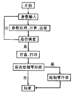
According to the composition and function of the threaded CAD, a program module integrating thread selection, strength calculation, check calculation and drawing is compiled by using AutoLISP language and C++ language. Finally, the design specification and parts drawing can be saved according to the user's request. The programmed program uses a modular approach to maximize readability, interactivity, and extensibility. The program flow chart is shown in block 3.
 Figure 3 program flow chart |
The dialog box is currently the most popular human-computer interaction interface. It supports input devices represented by raster scan displays and mice, providing users with a visual environment where graphics and text coexist, and the operation is natural and concise. The system makes the user interface as foolish as possible, and the user only needs to input parameters at the prompt to realize the design of the part, check the calculation and automatically draw the part drawing. The interface design uses DCL (DIALOG CONTROL LANGAAGE), which is a dialog control language. However, it is not enough to use the DCL language to compile the dialog box. You must also program an AutoLISP program to drive the DCL dialog box to make each dialog box. Controls have certain functions and meanings.
Thread design and drawing are connected by data transfer methods such as database, data file or global variable. When the design meets the requirements, the corresponding part drawing can be drawn at the same time.
You can choose to save or print according to your needs.
- Dialog technology and processing
- Determine the data that the application needs to enter;
- Analyze each piece of data that needs to be entered to determine which control to use for each piece of data;
- Layout according to the selected control according to the primary and secondary relationship and aesthetic point of view;
- Write a DCL file;
- Write an application processing dialog.
- File saving technology This program is written in AutoLISP language, and finally requires a design specification and part drawing. To save the specification in text form, the AutoLISP language provides a special function:
Getfiled("select a txt file" "" "" 1)
Calling this function will bring up a dialog box, select the appropriate folder from the dialog box, and close the dialog box by entering the file name in the text box. The function then returns a file name, which is the name of the file you entered. Then open the file with the open() function so that you can write to the data using the write function write-line().
- Document printing technology
In the Windows Windows environment, there are two ways to use the dialog box technology when developing AutoCAD. One is to use the dialog box technology of Windows, and the other is to use the programmable dialog technology provided by the English version of AutoCAD2000. The author uses the latter, the design steps of the dialog box are:
The AutoLISP language provides functions for working with dialog boxes. These functions can load dialogs from DCL files and assign initial values ​​to the controls in the dialog box, get user input in the dialog box, and define user-related operations.
Design specifications, parts drawings and simple assembly drawings can be printed according to user requirements.
AutoCAD is a powerful microcomputer drawing software that is popular among users. However, it cannot be fully utilized in China without direct development. AutoCAD has the ability to exchange data with high-level languages, that is, high-level languages ​​can read graphic data generated by AutoCAD. Conversely, AutoCAD can also accept data generated by high-level languages ​​and generate graphics. Only by making full use of this feature and carrying out secondary development, can it be made into a CAD application software with design features that is unique in various industries, so as to achieve the full play of its powerful functions.
LED light bulbs have revolutionized the way we light our homes and workplaces. Rather than relying on outdated incandescent bulbs, we can now enjoy the benefits of energy-efficient and long-lasting LEDs. One of the greatest advantages of LED technology is its versatility, which is reflected in the wide variety of LED bulbs available on the market today. Whether you need dimmable bulbs for mood lighting or small screw bulbs for tight spaces, there's an LED solution for every lighting need. Other popular LED bulb types include the MR16 bulb for spotlighting and the E12 LED bulb for chandeliers and other small light fixtures. With LED light bulbs, you can enjoy bright and beautiful lighting while also saving money on your energy bills and reducing your environmental impact.
Dimmable Led Bulbs,Small Screw Bulb,Mr16 Bulb,E12 Led Bulb,Small Light Bulbs
Ningbo Le Monde Import & Export Co., Ltd. , https://www.nblemonde-lighting.com